#132 Designing a Radio Repeater Monitoring PCB
About a year ago I realized the need for a dedicated repeater monitor that’s isolated from my clubs ham radio repeater equipment. E.G (power supply VOTER and Radio equipment). Having a dedicated monitoring PCB with a few extra complimentary features like remote control switching and reading/triggering capabilities would be very useful for largely remote and isolated places, also I get to test out and make some cool stuff.
So I convinced myself to make the RRM V1.0 radio repeater monitor based around the well known and beloved ESP8266. Well what about the ESP32 you may ask? Yes I have made a new and improved version with asynchronous reporting and many other hardware improvements however I intend to sell that as a commercial product and thus I will not be giving away to many details for free but for a small fee you too could have one in your hands so now hopefully you see my simple strategy.
Though I designed this board for monitoring repeaters it can also be used to measure current temperature and control inputs and outputs for a number of other appliances like monitoring the current, temperature and input outputs of a vehicle. With the WiFi capability the device can be connected to as an Access Point as well for mobile operations, of course connections to the internet through WiFi is required to send the sensor and peripheral data to the server so that reports and nice colourful charts can display the data in a useful logical manner.
Here you can watch a YouTube video where I discuss the design at our Ham radio bimonthly meeting a few months ago
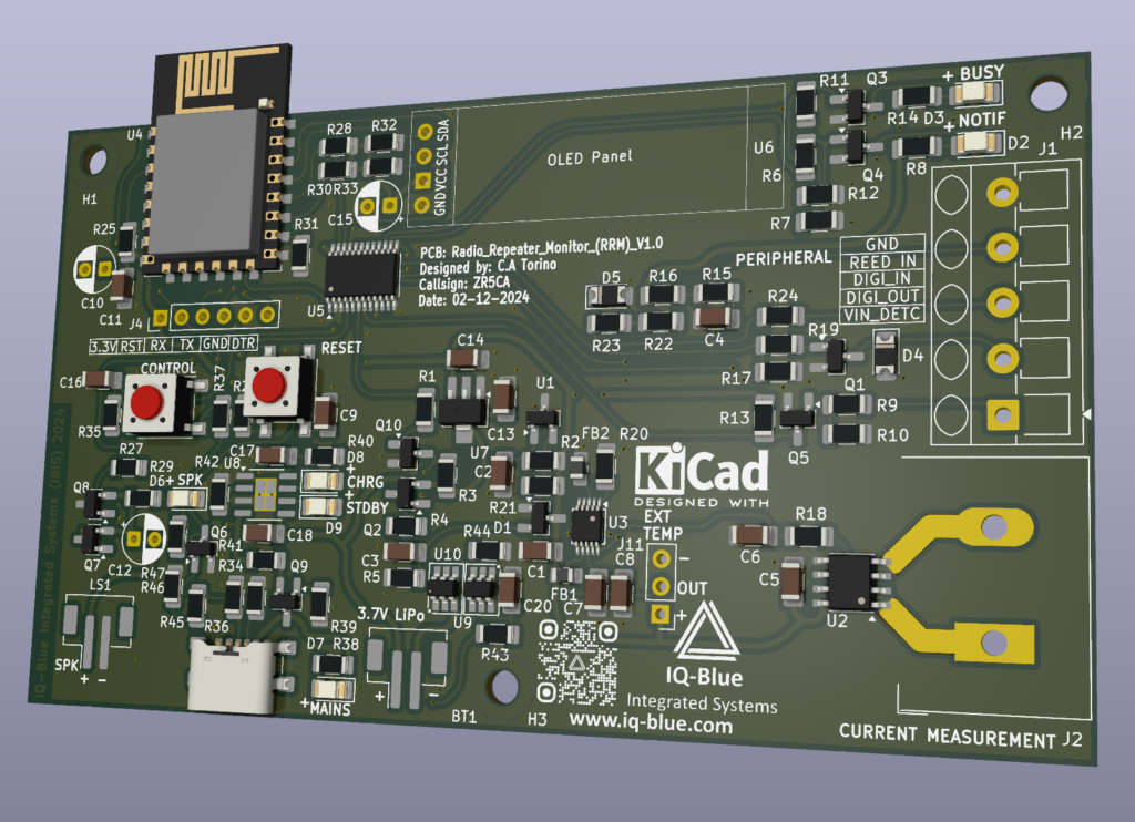
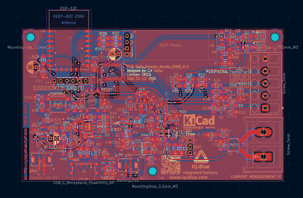
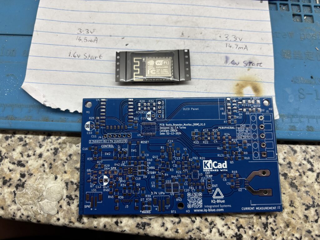
I decided to make a version 1 SMD PCB with large 1206 components as a prototype just to see that everything works correctly. I chose KiCad as my design software and got to work.
My requirements were:
- 1206 SMT Parts
- Current Measurement
- Internet Capability
- Reed In Detect
- Digital Input
- Digital Output
- Voltage In Detect
- Battery Back Up
- Temperature Sensors
- High Resolution ADS1115 ADC
- IO Expander
- OLED Screen
- Reset Button
- Control Button
- M3 sized Screws
- USB-C
- Buzzer
- Notification LEDs
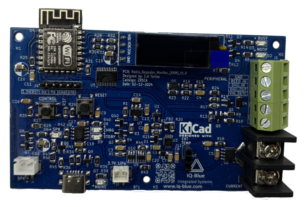
So I got down to work and created a prototype around the an ESP8266 module. Note: although this module has been around for a while there’s a lot of different variants available however the EPS32 will be used in my commercial version as it has much better performance and features as well as long term support.
Designing the PCB took a few weeks of fulltime checking and double checking and then triple checking XD. Then eventually I send the PCBs to be manufactured. I soldered everything myself and confirmed everything was working correctly. Next I just experimented a bit with different components, led colours and temp sensors etc.
Now I was ready to Install the module for tests at my local repeater site. We have WiFi and power at the site so I was able to connect all the hardware up and make things look neat.
Everything worked well and has been for over a year now so the project is a success I just need to monitor it long term.