Tag Archives: RADIO

RADIO REPEATER MONITOR

#132 Designing a Radio Repeater Monitoring PCB

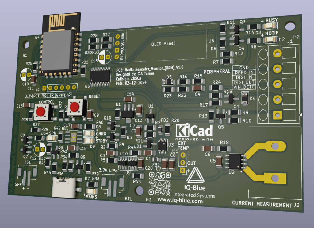
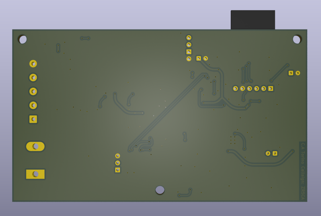
3D model of the PCB

About a year ago I realized the need for a dedicated repeater monitor that’s isolated from my clubs ham radio repeater equipment. E.G (power supply VOTER and Radio equipment). Having a dedicated monitoring PCB with a few extra complimentary features like remote control switching and reading/triggering capabilities would be very useful for largely remote and isolated places, also I get to test out and make some cool stuff.

PCB design

So I convinced myself to make the RRM V1.0 radio repeater monitor based around the well known and beloved ESP8266. Well what about the ESP32 you may ask? Yes I have made a new and improved version with asynchronous reporting and many other hardware improvements however I intend to sell that as a commercial product and thus I will not be giving away to many details for free but for a small fee you too could have one in your hands so now hopefully you see my simple strategy.

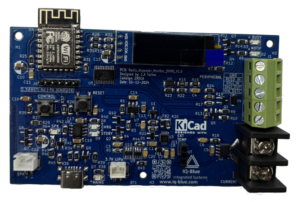
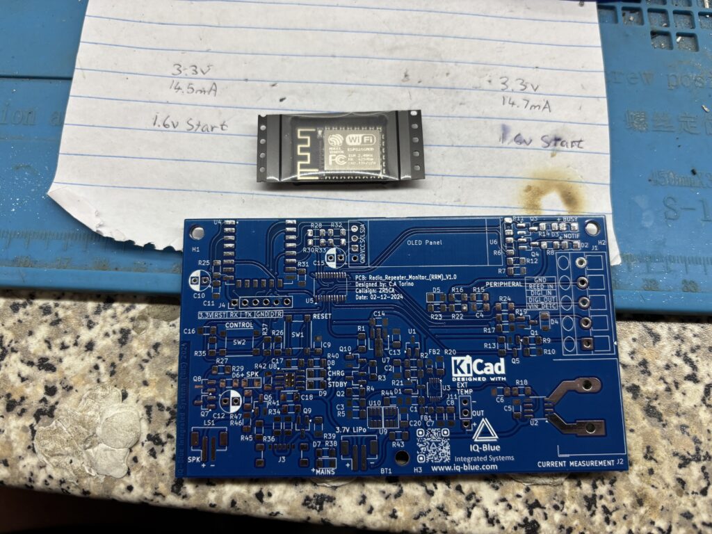
Soldered PCB

Though I designed this board for monitoring repeaters it can also be used to measure current temperature and control inputs and outputs for a number of other appliances like monitoring the current, temperature and input outputs of a vehicle. With the WiFi capability the device can be connected to as an Access Point as well for mobile operations, of course connections to the internet through WiFi is required to send the sensor and peripheral data to the server so that reports and nice colourful charts can display the data in a useful logical manner.

Here you can watch a YouTube video where I discuss the design at our Ham radio bimonthly meeting a few months ago

I decided to make a version 1 SMD PCB with large 1206 components as a prototype just to see that everything works correctly. I chose KiCad as my design software and got to work.

My requirements were:

  • 1206 SMT Parts
  • Current Measurement
  • Internet Capability
  • Reed In Detect
  • Digital Input
  • Digital Output
  • Voltage In Detect
  • Battery Back Up
  • Temperature Sensors
  • High Resolution ADS1115 ADC
  • IO Expander
  • OLED Screen
  • Reset Button
  • Control Button
  • M3 sized Screws
  • USB-C
  • Buzzer
  • Notification LEDs
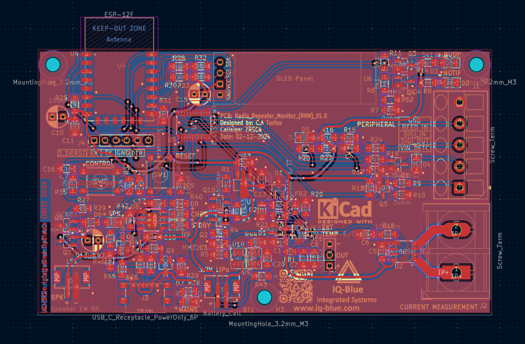
3D back of PCB

So I got down to work and created a prototype around the an ESP8266 module. Note: although this module has been around for a while there’s a lot of different variants available however the EPS32 will be used in my commercial version as it has much better performance and features as well as long term support.

Designing the PCB took a few weeks of fulltime checking and double checking and then triple checking XD. Then eventually I send the PCBs to be manufactured. I soldered everything myself and confirmed everything was working correctly. Next I just experimented a bit with different components, led colours and temp sensors etc.

Bare PCB

Now I was ready to Install the module for tests at my local repeater site. We have WiFi and power at the site so I was able to connect all the hardware up and make things look neat.

Everything worked well and has been for over a year now so the project is a success I just need to monitor it long term.

DUAL BAND ANTENNA FIX

#127 Fixing a Faulty Handheld Antenna

A while ago I purchased a few hand held radio antennas from a reputable source. Unfortunately one of them had a great SWR for 2m but a terrible SWR for 70cm. So I began investigating this and started to take apart the antenna to find out more. Just as a side note: I would not recommend this for beginners or businesses (if you have a faulty product immediately contact the seller and get a replacement or refund)

So during my autopsy of the antenna I was able to determine a few things. Firstly the plastic connectors in the middle of the antenna is supposed to have a loaded coil but there was just a crimped thinner antenna wire. Second on opening up the base of the antenna I was surprised to find out that they had a metal enclosing case which was nice.

Then looking at the SMA connection to the antenna I was pleased to see a base tunning coil and capacitor, this is a good sign. potentially meaning the antenna is a “GOOD COPY” of whatever the original antenna was. the antenna has zero markings but we can take a guess that its a good copy of the Diamond RH951

Finally I found the culprit.. the capacitor on the coil seemed to be destroyed.. after de-soldering it and testing it turned out to be a faulty part. So in order to fix the antenna I soldered another cap with a close enough value.. (13pf instead of 12pf) and sure enough after putting everything back together a gluing it the antenna worked perfectly but did have a slight frequency shift when Compared to the others I had purchased.

still this is a mission success the antenna works perfectly in both bands and I’ve been using it for over a year with both bands and no issues.

ALLSTAR NODE

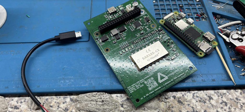
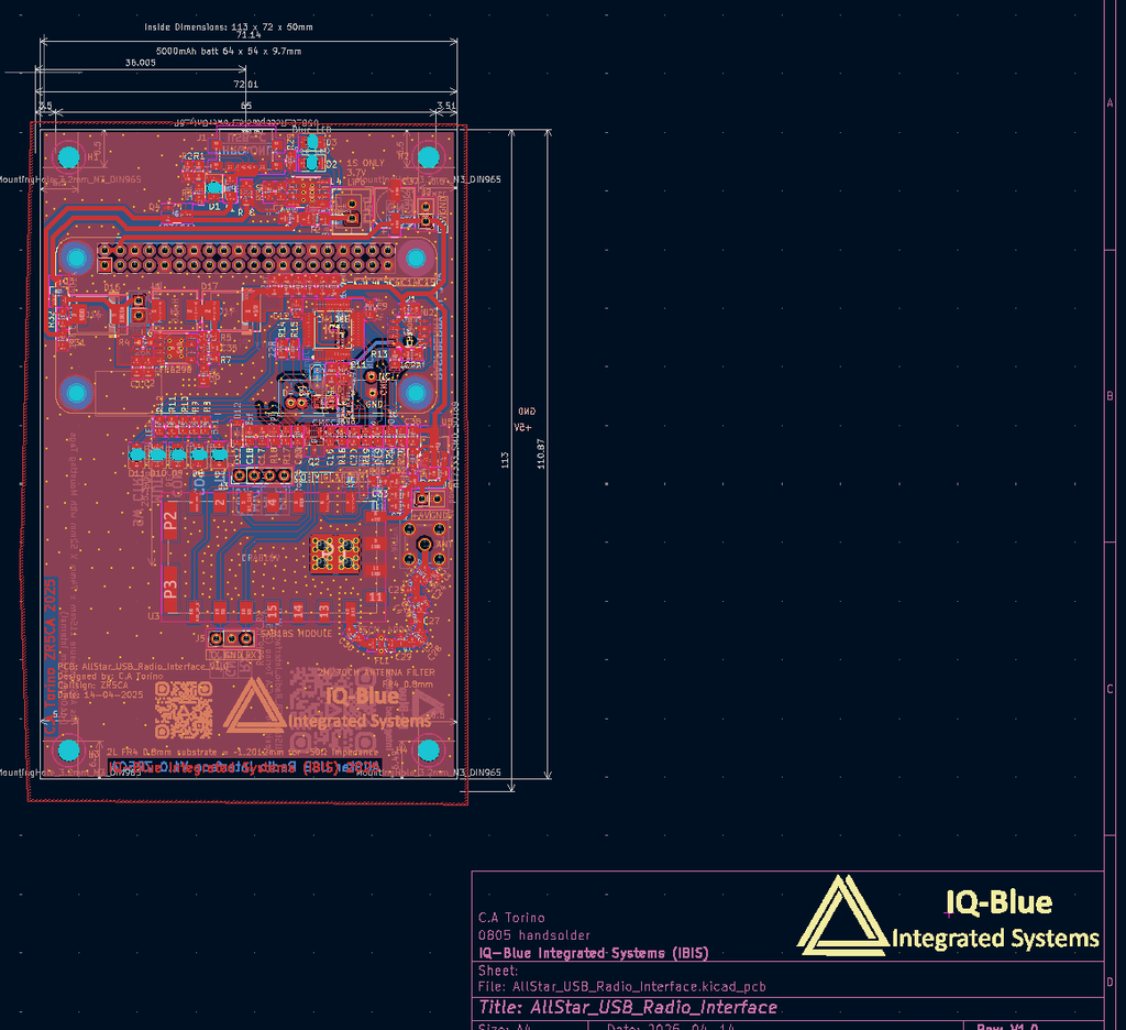
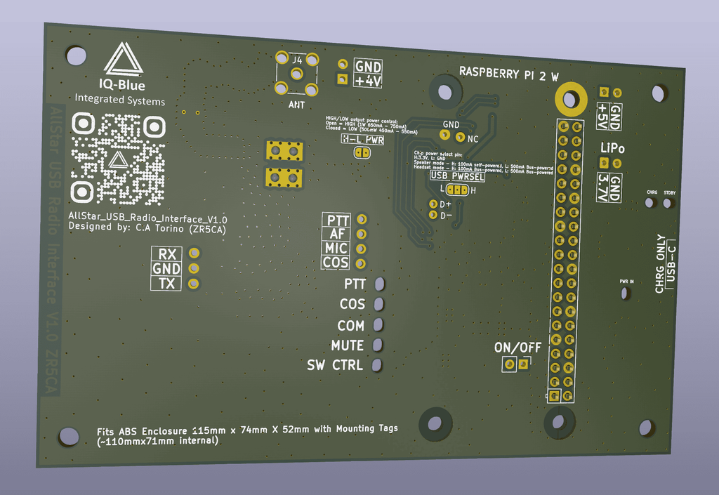
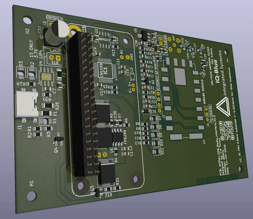
#126 Creating An Allstar Node

Display prototype on an actual Bread Board 🙂

In my previous article I was focused on the RTCM and the VOTER PCB which are used with repeaters. however I found out you could make a node instead for personal use. So basically a node is a radio connected through a sound card to a raspberry pi acting as an Allstar server.

You setup and connect this to the internet and you have a home made personal gateway to the Allstar servers. now you can listen or chat with anyone on the Allstar network

With that being said I was very interested in making my own version but I wanted it to use LiPo battery power for portability and a solar panel as power intake. I wanted a complete stand alone unit that could be setup once and placed somewhere and almost forgotten just remembered for maintenance and check ups.

I also wanted clean audio which could be a whole article in itself but for this write up I’ll be brief.

Testing out different filters and super capacitors
Eventually settled on a case with very short wires

I got the initial setup working using a UHF only Analog radio connected to a CM108 sound card that is plugged into a raspberry pi 2w with an OTG adapter. (it’s very important to keep all the wires as short as possible to prevent them from becoming antennas!!)
This was connected to a 5V step up converter and charger in 1 module. Now the radio needs max around 4.2V so I had to add an additional stepdown converter to accommodate this.

CM108 FOB

Everyting worked well and the system was portable but there was a very annoying whine. with some filtering I was able to reduce this significantly and the setup was almost done.

One annoying issue was that when the 5vstep up converter switched from main to battery power there was a very brief short delay where power to the raspberry pi could be lost casing a brownout and reboot of the pi. The solution was to add super capacitors in parallel with the supply to keep the volts flowing during this dip in power.

Also using a linear voltage regulator with a high ripple rejection circuit helped reduce the audio whine and noise

Over all this was a fun success of a project I will be creating a permanent case for my DIY version and I will be creating my own custom Nodes with a professional PCB for sale in future!

COS wires location on the radio
RX, PTT and GND solder areas

ALLSTAR VOTER

#125 Creating a DIY VOTER

Unpopulated VOTER PCB from the factory

VOTER (Voice Observing Time Extension for Radio) 

For a while now I have been involved with some troubleshooting at my radio clubs repeater site closest to me.
we have had a few issues where our equipment gets damaged from lightning water and rats.

We’ve tried to mitigate these problems however the reality is that it more of a manage the symptoms situation rather than solve the problem situation.

With this in mind we have had some damaged RTCM devices, the RTCM (radio thin client module)
is connected to the internet and to the repeater. It has an IP address and forwards the voice data to other sites or nodes that have the Allstar system setup. It’s basically like a small VOIP system that can adjust squelch and do simulcasting but the repeater site can choose what settings to enable or disable.

In our case its just connecting the Voice data to the internet so that club members can chat with other repeater/node users over a greater distance through the internet.

E.G: talking to someone in Durban is not possible using VHF at the altitude where I am situated, due to the terrain, large mountains and a hefty over 100Km+ distance away VHF will have a really hard time. Also with all the solar whether these days… I would expect diminishing results.

But… with an RTCM connected to a repeater or a Node, I can now communicate over that distance using Analog VHF radio to the RTCM over the internet and then through the repeater or node on the other side in this case in Durban.

Checking and adding components to the PCB

So now the big issue I had was that RTCM devices will be just under 10K south African ZAR from America for 1 with shipping and all the tax applied it’s very expensive and I wish money was no object but the truth is our club is not super financially inclined due to many reasons a lot of them out of our control.

This prompted me to investigate on an alternative and I found a few but I chose the original 2011 VOTER PCB which allows us to do the same thing basically just on the prototype board.

Of course this rises some concerns like:

  • THT components used
  • Parts are all PDIP and most have to be substituted
  • No case provided
  • A larger size
Back of the PCB while I was populating it

But… in my case weighing up the pros and cons there’s no major issue using this VOTER version.

So I got a few professionally made, read the datasheets for all the IC’s and purchased the available parts.
I also substituted the parts no longer available and integrated them with some small modifications.
(I will create my own PCB based on this in the future for better availability and usability)

Overall It took me around 3 month just to read all the datasheet and to get familiar with they systems bootloader and firmware of the VOTER PCB not to mention learn about the Allstar system as I had not really been educated on it. Though it was worth it and the research paid off in the end.

I was able to learn fast and I can say that I was happy with this project and the VOTER boards turned out great!!

Front of PCB while I was populating it.

DIY LORA MODULE

#115 Making A DIY LoRa Module

2x DIY LoRa RFM95W modules with adapter boards.

When taking a closer look at the DIY aspect of lora I wanted to test LoRa peer to peer.. E.G multiple peers to one peer (NOT LoRa WAN) I noticed that the actual radio PCB is difficult to use when going the traditional through hole way… adapter boards do exist but are few and far between at least in SA. you can make your own for manufacture but then rather create your entire product PCB for manufacture.

Even with this drawback I was able to source old adapters for one of the very firs modules the: RFM95W. In South Africa we are mostly using 868Mhz although 433Mhz modules are around I don’t see them being super common in terms of LoRa modules.

The modules I used have a footprint for adding a female SMA connecter for easy antenna connecting.

Parts used:

  • 2x RFM95W 868Mhz LoRa module transceiver
  • 2x 3.3v active buzzer
  • 2x 1 pole dip switch
  • 2x TP4056 module with protection ICs
  • 2x ATtiny404 MCU
  • 2x NCV8163 3.3V LDO
  • 2x SSD1306 128×32 OLED
  • 2x 2pin 2.5mm JST battery connector
  • 2x Headers and jumpers
  • 2x 13400 3.7V 550mAh
  • 2x 10k resistors
  • 2x 220R resistors
  • 2x SOIC to DIP adapter PCB
  • 2x BC547 transistors
  • Some 0.9mm tin plated copper wire
  • Some 0.255mm PVC insulated wire
Soldering made slightly easier…

After checking the PCB I commenced with testing the devices. Unfortunately the test area has largely mountains terrain
the signal works really well and penetrates better through foliage on the mountains terrain but once there is a full on mountain in the way the signal stops. so in this retrospect the devices are better then a radio which was quite interesting but makes sense because data is being sent and uses less bandwidth then interpreting voice audio. Also the error checking for LoRa helps a lot.

Some more pros for the LoRa is that its a transceiver out of the box with RSSI functions included. Also for increased range and/or quality the spreading factor and signal bandwidth can be adjusted.

Although there’s many pros regarding LoRa I still tend to use simple 433.92 RF modules without issue at least in my situation with rural areas under about 3KM at and given point.

So it really becomes more of a cost factor than anything else. Although I’m happy selling a custom LoRa product for compatibility with LoRa WAN or some other requirement with a similar principal. Plain old generic RF is still cool in my book.

Back of one of the PCBs

COMMON RF MODULES IN SOUTH AFRICA

#109 Types of 433Mhz RF modules in ZA

FS1000A module at 5v no attenuator just using antenna.

Recently I have been using wireless technologies for a few projects.

While looking for a balance between price, functionality and disposability I decided to focus on the 433Mhz RF modules.

These use a free spectrum and have been around for a long time. There’s is a few different types and kinds, with LORA being kind of new and better in almost every way but this comes at a high price compared with the standard 433 RF modules.

So I purchased a few receivers and transmitters from electronics suppliers located in South Africa.

All my tests consisted of running the 4 receivers at 5v and a single 17.3cm straight LAN cable strand as an antenna. The signal sent was a 23bit ASK signal with a pulse length of 1200ms.

All 3 transmitters were tested at 3.3v with a single 17.3cm straight LAN cable strand as an antenna.

The transmitters testes were the FS1000A, CYT1 and the WL102-341.

The crude module actually has more power and range at 5V but I am using them at 3.3v for super low power applications so In this case the module loses.

The Tests were done on farm land.

All transmitters could trigger the receivers at 400m line of sight but only a few could penetrate foliage and a galvanised steel shed.

I only needed MAX 400m which is why I stopped there but some sources claim up to 600m – 800m + for these superheterodyne modules. Not as good as LoRa but for the price what reason do I need not to use them?

*Sidenote Using RF or LoRa in conjunction with a 2.4G Wifi module like the ESP32 or even 3G/4G modules can create multi dimensional divers systems. where we are leveraging the long range and penetration + power output of 433Mhz and 868Mhz but also allowing packets of data to connect over the internet to be stored on a server for data analysis and the creation of graphs to make the data more visually appealing.

Currently I do have some pilot devices and hope to one day make some good quality sensors in 3 different tiers:

  1. Cheap and disposable sensors
  2. Affordable long term sensors
  3. High end sensors

These will be focused on use within rural outdoor areas and I will have a version with Gerber files and schematics etc. available for anyone to download and make for themselves. However the more refined version with a nice enclosure and style will be sold commercially since I do want to be paid for my work.

Back to the modules..

The transmitters that support 5v could penetrate a little better sometimes.

The position of the transmitter/receiver could also greatly affect the received signal especially at range.

Also during summer and during rain the signal was worse with the foliage and water most likely absorbing and/or reflecting the signal

All receivers were superheterodyne with a crystal and I did not use any counterpoise though it would help in some circumstances it makes the receiver unpractical and large.

From worst to best

Some people may wonder why I am using these modules instead of the fashionable LoRa modules. This is simply due to cost and availability.

Designing a good circuit cost time and money. Inserting said circuit into an extremely hostile environment like for example.. rural South Africa is an even more costly exercise

I have had devices damaged by the sun, damaged by water, damaged by ants, damaged by cows, damaged by some kind of rabid animal (assuming jackal) The list goes on.

AND I have not even mentioned the human element… devices damaged by criminals some even STOLEN… for what? You telling me that criminal is sitting in the bush conspiring to reverse engineer my simple circuit and RF protocol and some how will be able to defeat Microchips code protection? I highly doubt it but it is possible…

So now I hope you can understand why these cheap modules do work and are very useful + inexpensive for my purposes.

I also have LoRa versions but for now I only use those when distance and extreme sensitivity is needed.

MOTOROLA CM140

#102 Reprogramming an old CM140 radio

Motorola CM140 From 2003.
Testing shows great results.

If you do not have the code plug password or a saved code plug with the radios serial number then this post is for you.

I recently came into possession of 2 Motorola CM140 25W radios. These radios belonged to my grandfathers old security company which is now dissolved, however amongst a lot of the kit I was able to save a few gems.

Upon inspection these radios were in immaculate condition despite there age. I was able to power up both radios only to find that they were programmed to one channel and when I used Commercial Series CPS (customer programming software) I could not read or write to the radio since the code plug was password protected.

Luckily I found a sample code plug for the model of CM140 radio I had. This allowed me to clone and change the password of the radio using the sample code plug now I can read/write to the radio

I have created a step by step document on my GitHub page here.

Schematic For The Programming Cable. Updated to V1.1 on the 3rd of April 2025
Any 5v TTL Device Can Work.

LORA SETUP

#78 Setting up the LoRa T-Beam

Living on a farm I often encounter communication issues coupled with the urgency to communicate when catastrophes strike. Therefore in my quest to find suitable backups and backups to the backups I stumbled upon the LoRa system. Specifically the LoRa boards in the T-Beam configuration using the Meshtastic firmware + Android app which allows text message communication over a few kilometers in my case.

After testing them I came to the conclusion that they do work and reliability, however they can get damaged easily and the quality of boards and components used is not up to the bar of commercial motherboards such as gigabyte PC motherboards as an example.

My final opinion being: they work and I would use them as one of my “coms” layers however I would not put the T-Beam on par with a mobile phone the quality is simply just not there.