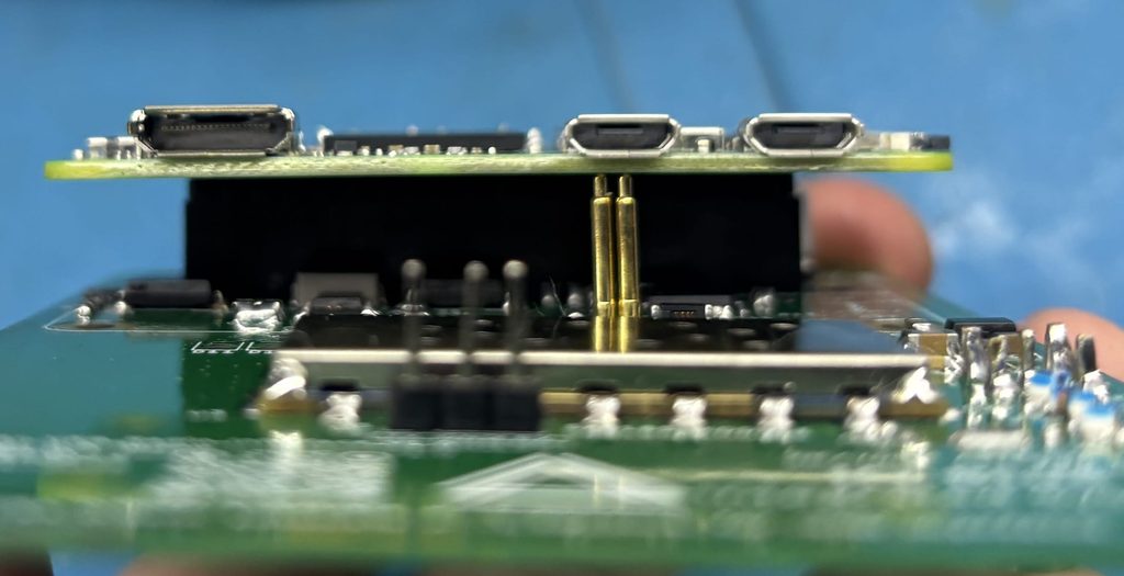
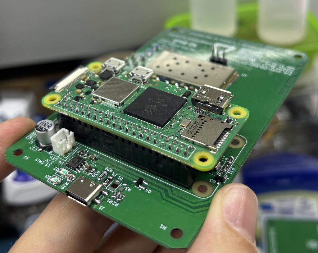
My prototype using a LAN cable breakout enclosure made it small and nifty.
A few years ago while using many wireless systems on a large remote property I had the problem of testing the signals in varies areas before installing my hardware like: Roboguards or my own custom devices that have the ability to communicate with the RoboGuard ecosystem.
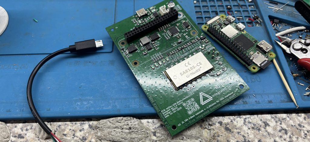
Front view of the PCB. It fits perfectly into an ABS enclosure.
So I decided to create a dedicated remote that uses the ASK protocol used with these devices. This makes my life so much easier because it allows me to test multiple requirements at once.
I’m able to test:
Signal strength in the area
433 modules I want to use
Antennas I want to use
The transmission logic I want to use
Different ASK protocols
All this with a wireless, rechargeable and easily customizable package. At the moment this is not a commercial product however I have many other devices that work with the Roboguard ecosystem that have commercial applications.
Back view of the PCB. This was made around the ATtiny212 MCU and the SYN1115 transmitter.
While looking for a good example PCB project I decided upon a simple UPDI programmer PCB for the well known new ATtiny ICs. I had a few prerequisites I wanted to satisfy for the project.
Design must work but also have room for improvement
small SMD PCB design
BOM list and prices
simple schematic using KiCad
1206 component size sop-8 IC size
USB-C
2 sided PCB
all standard sizes for PCB manufacture
PCB panel example
Front
Back
I wanted the project to cover many of the basic and intermediate PCB manufacturing practices of course the IC is not very sophisticated and there is no impedance matching or equal length traces etc. However it shows how designing, quick and affordable manufacturing can be achieved in South Africa. Designing for manufacturing, thinking of the capabilities of the manufacturer and keeping best practices in mind at least to the best of my knowledge at that specific time.
In the project I keep things as standard as I can using metric measurements and easy milling panel design for the panel (no fancy curved edges or designs) although many interesting looking designs can be made surprisingly simple, it takes experience plus CAD artistic intuition. That being said I wanted this to be a simple and practical example I could use for teaching references later.
Getting to the component choices for a small UPDI programmer I chose the CH340N IC. It needs very little external components and has an internal crystal. Small and lightweight and perfect for my UPDI project. It is missing other pins like the reset pin but in my case this was not an issue. Always double check your IC datasheets and capabilities.
KiCad modal front
KiCad modal back
On that note I did receive some FAKE CH340N ICs and I tested them. They only worked on lower baud rates and adding LED indicator resistors to the TX and RX made them unstable. Unfortunately in this day and age fake ICs are very common you need to recognize them and weigh the balance between using them or not. Sometimes there’s a “good fake” so as a maker I may use this test projects or make throwaway projects but the characteristics of the IC are now different so any calculations are incorrect… so it’s a balancing act that no-one can escape. For production always use IC’s from the original manufacturer the stores are easily found online and it’s worth it in the end.
Simple schematic
All other components are very basic 1206 (easy to solder) SMD capacitors, resistors, TX/RX LEDs, power indication led, a diode 16-pin USB-c connector with 5k1 sense resistors keep the PCB copper balanced on both sides also saves etching chemicals for the manufacturer I also added some example fiducials and the copper stops 1mm from the edge of the PCB creating a small protection layer all around.
Since there is a USB-C connector I chose not to include any ESD or fuse but I would add these components to a commercial variant.
Also this v1.0 has the TX/RX LEDs on the wrong indication pins. I would change them to the USB side instead.
Overall I think it’s a good introductory example showing a simple design including some errors and fixes.
When getting into the new ATtiny series (tinyAVR-0 tinyAVR-1 tinyAVR-2 IC’s) of microcontrollers a few years ago I noticed how easy it had become to program them with only a few extra components.
I started out with just a 4.7k resistor and a cheap CH340 programmer. Then 3 wire hook-ups later I could easily program my IC’s. The only downside was that I had to sacrifice the UPDI pin to the dedicated Pin gods.. so I couldn’t use that pin unless I wanted to make my life more difficult.
Well this was okey for me and ever since I always have the UPDI pin open only for programming. So all my designs incorporate this principal. If I really need more pins I would use an affordable IO expander IC.
Now with that being said it’s all good and well programming with a mini rats nest… but I wanted to create a simple plug and play DIY programmer with commonly available parts and plug and play compatibility.
So I came up with a small circuit that’s easy to build on stripboard. I created a few versions over the years. Since I was the only one using this contraption I didn’t think of creating a professionally made PCB but that will come in future..
Front of the stripboard
Back of the stripboard
How do I use this?
Basically I solder the SMD package ATtiny to a suitable breakout PCB then I plug the ATtiny breakout PCB into my programmers female headers making sure the orientation is correct and presto all I need to do is upload my firmware. Then I can just remove the PCB and Plug it into my project
Simple and to the point… plus it’s been working for years.
Version 1.0 of the protoboard not as appetizing as the schematic…
Reverse side with thicker black wires for the MosFets.
Creating a a custom 4ch Mosfet switch PCB with a built in backup 12v battery changeover circuit takes some careful planning. Since I had experience working with mechanical relay versions the task was not too difficult however it did come with a few extra challenges. Mosfets require more parts to work reliably they also have significantly different ratings when compared to relays. In this case I was using an esp8266 with 3.3v logic. I had to create an amplifying circuit out of two transistors in order to get around 6.6V to allow the Mosfets to turn on completely thus allowing me to utilize their max current ratings.
The beginning of prototyping always looks so clean…
Bread Board prototyping is always a good idea before soldering.
On my 4ch PCB I used 3x IRL520N and 1x IRLZ44N N channel Mosfets. The IRLZ44N is the best rated for logic level and also the most expensive and rare here at least at this time. I also needed a large amount of amps for the LED strips it was going to switch on and off. The other three IRL520N Mosfets will be used with applications using under 5A of current. Technically I could have just used TIP120 NPN transistors but I wanted to keep the entire PCB Mosfet compatible in case I wanted to swap out any chips.
Drawing block diagrams by hand help the though process.
Creating a clean schematic in KiCad makes building the board easy.
For more info on the project check it out on Github
Since I used low voltage with nichrome wire using LAN (RJ45) cable was not an issue. However with the next version I will solder a female RJ45 socket to avoid the hot glue tsunami… 🙂
Creating a WiFi fireworks igniter with a backup LiPo battery.
With December just around the corner I wanted to design a remote fireworks igniter working on WiFi and battery power.
The board will use mosfets as switches to nichrome wire which will heat up and ignite fireworks from a safe distance.
Before completing the PCB
The idea is to have the system self contained with the ability of remote control via a WiFi AP using an ESP8266 12F
The link to my GitHub repository (containing the design, parts list and other files) can be found here.
With the ever growing pains of load-shedding looming over South Africans people have been desperately looking for viable alternative energy and battery powered devices. In my case I needed my remote pepper spray devices to be operational in my laboratory even during extended load-shedding times 4h off with 2h charge times.
I could have purchased added a battery and charging circuit to my existing factory made Sonoff board however that could make the PCB larger and I wanted to build a custom solution instead.
My requirements were WiFi capability, at least 4 relays, li-ion battery powered, battery charger with all the standard protection features and for the device to be powered by 5v from a standard phone charger.
The device must be plugged into the 5v phone charger 24/7, when the electricity goes off the device must continue to operate uninterrupted, when the power comes back on the device must change to the charge state uninterrupted.
The device does not have to send a notification when using battery but it must protect from overcurrent and over-discharge.
While looking for components I came across the ESP8266 PSB 04 module which is basically just the MCU WiFi controller used to switch 4 channels by itself
This was perfect for my application because I am already very familiar with Sonoff devices and in this case I do not mind using the firmware on the esp8266 and the Sonoff application + API software for my automation tasks.
Building around the module was a breeze all I needed was the appropriate relay circuits and a decent charging module.
I ended up creating two prototypes because hey there’s always improvements to be made…
Drill holes for terminals and relays
ESP8266 board with buttons, led and 3.3v regulator
Headers to mount LiPo and ESP8266 boards
The components I used on my final version 1.1 are as follows:
I tried to make the design as modular as practically possible
There are 3 main parts in the design consisting of a main PCB which contains the battery and relays = complementary components then the WiFi module with buttons and 3.3v regulator is located on a small green PCB and finally the LiPo MH-CD42 module can be secured on the main board via headers.
While constructing I had to use a 1.6mm drill bit for the battery holes and a 1.5mm drill bit for the relay holes. I soldered the SMD AMS1117 reg onto 3 a pin male header for easy through hole placement. The relays and the screw terminals required more attention during drilling and placement of the holes due to their pin layout. I also coated all exposed wires with nail varnish as a make shift solder mask.
I had to add an extra 1000uF capacitor between GND and 5v out of the LiPo module because it would briefly lose power when transferring from USB to battery power
After setting up a CCTV system consisting of multiple WiFi cameras placed over my property I noticed that certain cameras were located in areas far away from AC outlets covered by my backup electrical system.
In this project I used some an old 18650 (LG makes the LGABD11865 ) from a laptop power supply. Also I upgraded my 5v charger to a 1.5A to provide enough charging and running current for the camera. The camera I am using is the EZVIZ C3W 1080p WiFi camera
Since Load-shedding has been increasing dramatically I had the need to find cheap simple and reliable power sources for there cameras (12v DC). One important requirement is that the backup system needs to fit into a small area E.G an electrical box on a pole where the camera is located.
While researching I came across the so called mini dc ups device mainly used for backing up WiFi routers at either 9v, 12v, 15v, 24v. however these devices seemed a bit overkill electronically wise and also price wise.
So I decided to opt-in on a cheaper smaller sized DIY version the components consisting of:
The components are all soldered onto a 50mm x 70mm 1 sided PCB board.
I noticed that the 4056 IC gets quite warm but doesn’t burn my fingers. The same goes for the coil. The specification is max 1A and the load I was applying was around 0.33mA – 0.670mA
After testing this particular LiPo charger PCB I noticed a few major problems the first being that the 8-pin 4056 LiPo chip is a copy of a copy… the next critical problem is that there is no protection circuitry besides the overcharge/discharge function in the 4056 chip.
This is a big problem since the chip does not switch off completely when low voltage occurs and as a result the load will periodically switch on and off unreliably before finally switching off completely. This oscillation can damage the load.
A solution will be to use a separate LiPo PCB with protection mosfets and a separate booster board.
Upon experiencing a few break-ins on the farm I decided to look for a simple alarm system to monitor certain door. For such a simple project a full on alarm commercial alarm system would be overkill.. So I endeavored on the short and fruitful DIY journey.
My system is based on the simple circuit from Great Scott on YouTube. The brains of the circuit is the Arduino programmable Attiny85 MCU. A reset push button, notification LED, arm/disarm toggle switch, notification buzzer and magnetic read switch are the IN/OUT components used.
The project runs on 12 volts (12 volts for the siren) which is filtered down to 5 volts for the Attiny85. My plan is to use a 12 volts 7 ampere lead acid battery combined with a smart charge board to power the project effectively.
After soldering the components onto the board everything worked fine. However the siren was very soft and the 2N2222A transistor was getting extremelyhot. This is because the transistor has to provide a ton of current to the siren in order to get it working at 100% capacity. A quick fix is to remove the 1k resistor between Attiny85 pin 1 and the transistors base.(replace it with normal wire) This allows the siren to be louder but the transistor is still hot. A possible permanent solution will be to just use a 5v relay or look for a transistor with a higher current tolerance.
In the end I decided to go with a 5v relay module since it’s a quick reliable solution but is more expensive than a transistor. In a future upgrade I will most likely use a BC517 darlington as referenced by this article. It will be cheaper than a relay and provides more than enough current for a 15W 1 tone siren (380ma).