Tag Archives: REPEATER

PORTABLE ALLSTAR NODE

#134 Making a better Allstar Node
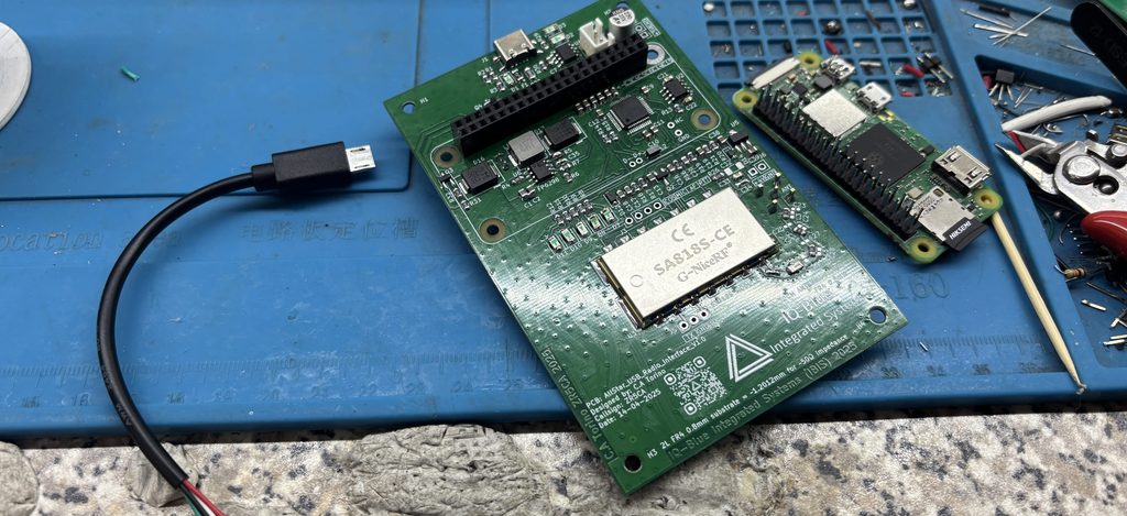
Soldered node and PI Zero 2W
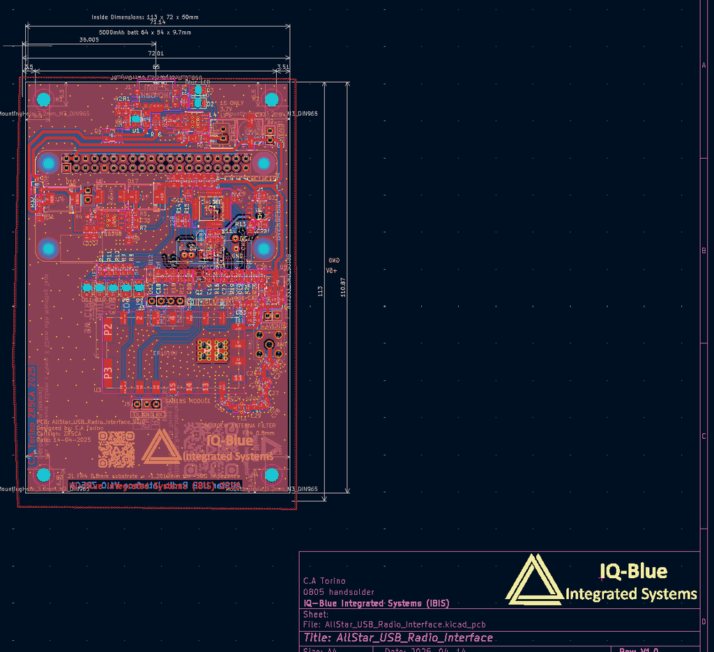
Kicad design
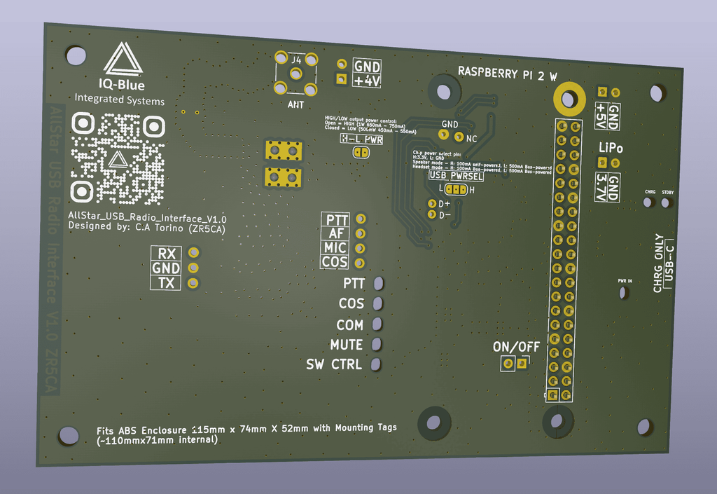
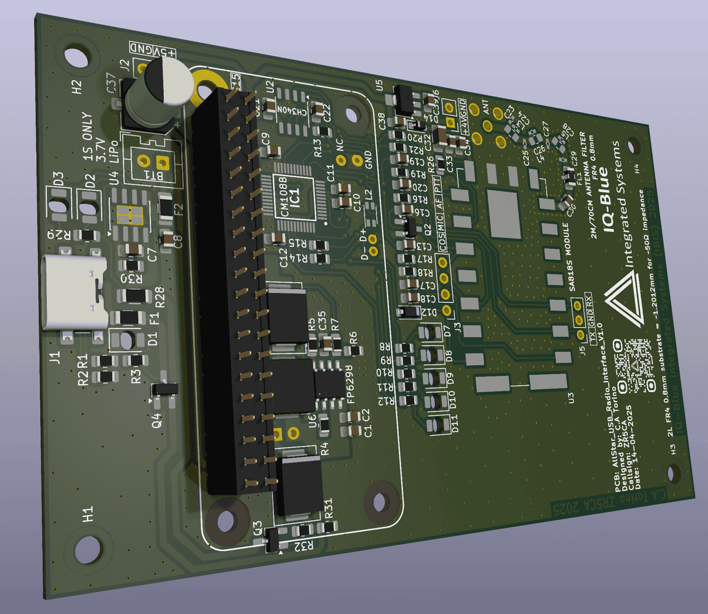
Front
Back

While looking for solutions to connect to my radio clubs repeater systems. I considered a few solutions, eventually I settled on the Allstar asterisk system. This allowed us to connect analog radio signals over the internet similar to traditional repeaters without sounding too much like a VOIP system.

The system was created by a ham for hams with lots of settings and capabilities as well as tons of customization options. This sounds complicated but it doesn’t have to be. The beauty of the system is that you can decide to just buy a node or voter or make your own hardware. There’s options to cater to a large range of ham operators, there’s even commercial licensing (asterisk) and systems for business operators which is also nice. Having options is always good in a robust communication network.
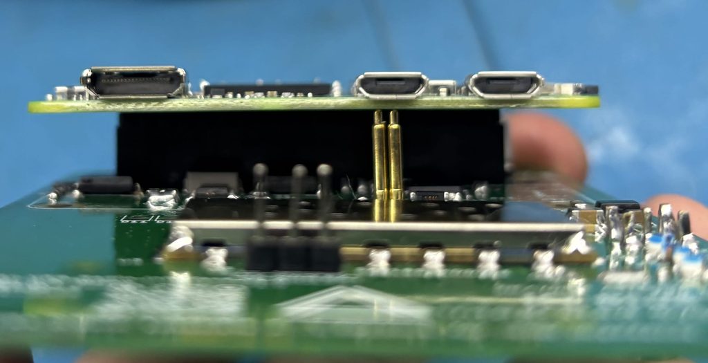
Pogo pins for data with a choke to filter the data lines

After making a few DIY nodes I wanted to make my own complete professional PCB node unit with quite a few requirements.

Namely:

  • 0805 parts.
  • Affordable and efficient as possible but also prototype friendly.
  • Easy layout for quick soldering.
  • Extra fuses and protection.
  • Reverse polarity protection USB-C.
  • Built in battery (LiPo pillow cells) commonly available & large capacity.
  • Short or limited no (wires flopping around)
  • Good grounding.
  • Good 50v or 35v capacitors.
  • Calculate PCB thickness/shielding and filtering for 50ohm impedance.
  • Solder bridge points and lots of headers for testing and debugging.
  • Antenna fits in a monopole way so try have decent ground plane.
  • Built in efficient linear charging circuit (avoid noise as much as possible)
  • Power path circuitry to allow charge and power (need good wall adapter)
  • Built in step up to 5v high current for PI and radio.
  • 5v step up converter with high efficient and frequency (min 500khz)
  • Use Raspberry PI zero 2W hat approach
  • Pogo pins for USB data & choke
  • CH340 type of UART to TTL IC for programming SA818.
  • USB differential pair tuning.
  • 4v linear regulator for filtering before powering radio module.
  • Uses SA818 modules (UHF/VHF FM capability)
  • Ability to connect any radio if needed (so not forced to use the SA818 module)
  • Proper radio filtering for UHF/VHF FM options.
Blank PCB top & soldered box below

After taking all these points into consideration I was able to do a bit of research and just a tiny bit of testing and then some more testing and then some more… Finally I was happy with the PCB I had sourced a decent box and design concept and all the parts allocated. I calculated all the costs at time of purchase and manufacture and sent to Gerbers off.

A few weeks later I was greeted with some decently manufactured PCBs.

On fitting the actual PCB to my enclosure I noticed the edges needed to have a more aggressive chamfer… Which I was able to do manually with a metal file tool. I did this outside with eye protection and a proper mask with respiratory particle filter. FR-4 carbon fiber dust in no joke.

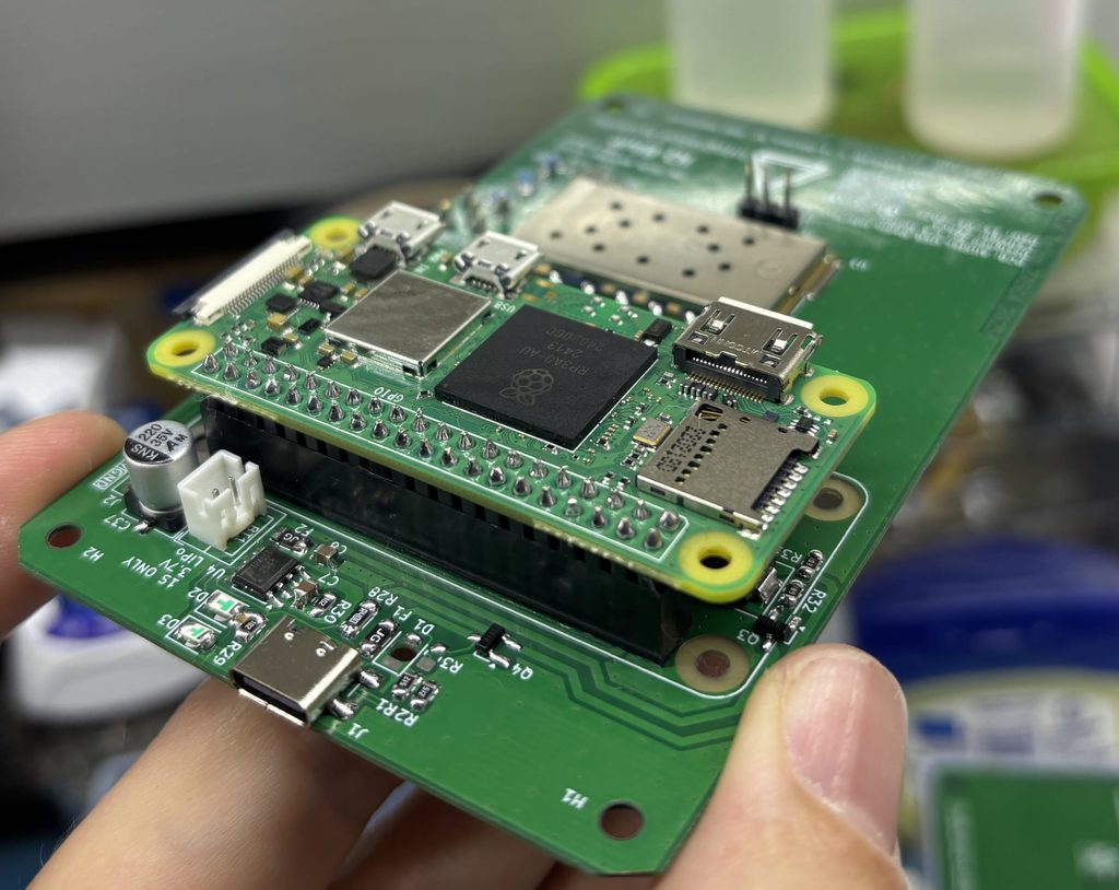
chamfered edges
PI close up

After about a year of testing and playing around with different configurations I’m quite happy that this project worked out really well.

The two biggest concerns are chip availability and time designing, researching and developing.

Creating a commercial version of any project or product has a few other challenges, the big one being “bureaucracy” sadly there’s not much that can be done and “the process” can never be trusted.. we can only suffer through it and hope to be a better person at the end of the day.

Video demonstration here.
RADIO REPEATER MONITOR

#132 Designing a Radio Repeater Monitoring PCB

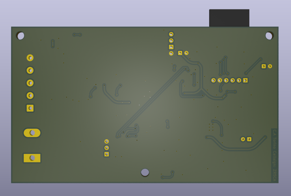
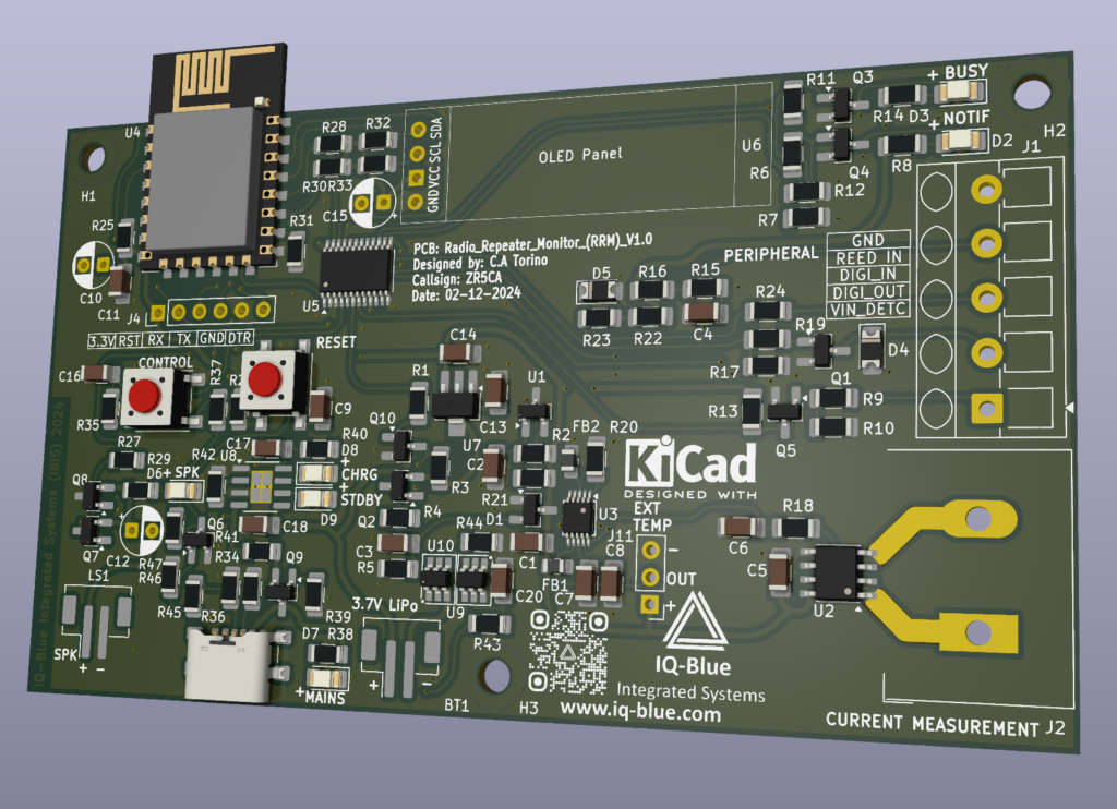
3D model of the PCB

About a year ago I realized the need for a dedicated repeater monitor that’s isolated from my clubs ham radio repeater equipment. E.G (power supply VOTER and Radio equipment). Having a dedicated monitoring PCB with a few extra complimentary features like remote control switching and reading/triggering capabilities would be very useful for largely remote and isolated places, also I get to test out and make some cool stuff.

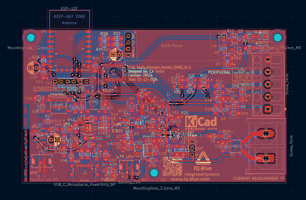
PCB design

So I convinced myself to make the RRM V1.0 radio repeater monitor based around the well known and beloved ESP8266. Well what about the ESP32 you may ask? Yes I have made a new and improved version with asynchronous reporting and many other hardware improvements however I intend to sell that as a commercial product and thus I will not be giving away to many details for free but for a small fee you too could have one in your hands so now hopefully you see my simple strategy.

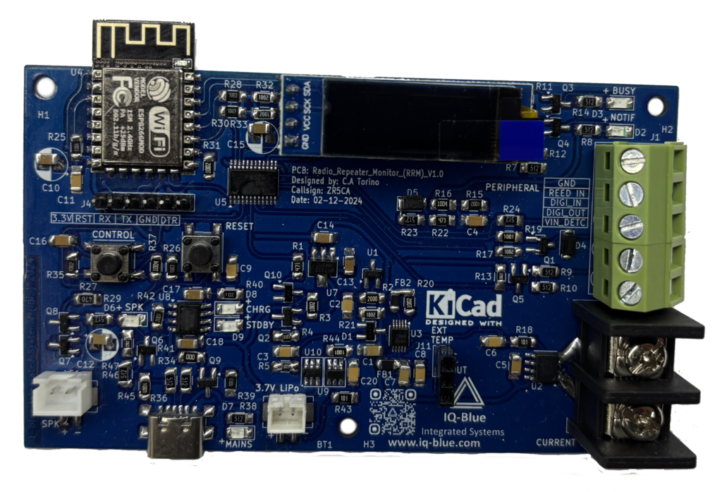
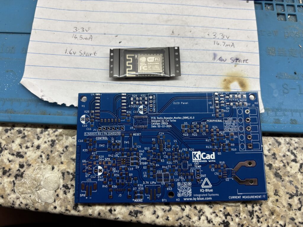
Soldered PCB

Though I designed this board for monitoring repeaters it can also be used to measure current temperature and control inputs and outputs for a number of other appliances like monitoring the current, temperature and input outputs of a vehicle. With the WiFi capability the device can be connected to as an Access Point as well for mobile operations, of course connections to the internet through WiFi is required to send the sensor and peripheral data to the server so that reports and nice colourful charts can display the data in a useful logical manner.

Here you can watch a YouTube video where I discuss the design at our Ham radio bimonthly meeting a few months ago

I decided to make a version 1 SMD PCB with large 1206 components as a prototype just to see that everything works correctly. I chose KiCad as my design software and got to work.

My requirements were:

  • 1206 SMT Parts
  • Current Measurement
  • Internet Capability
  • Reed In Detect
  • Digital Input
  • Digital Output
  • Voltage In Detect
  • Battery Back Up
  • Temperature Sensors
  • High Resolution ADS1115 ADC
  • IO Expander
  • OLED Screen
  • Reset Button
  • Control Button
  • M3 sized Screws
  • USB-C
  • Buzzer
  • Notification LEDs
3D back of PCB

So I got down to work and created a prototype around the an ESP8266 module. Note: although this module has been around for a while there’s a lot of different variants available however the EPS32 will be used in my commercial version as it has much better performance and features as well as long term support.

Designing the PCB took a few weeks of fulltime checking and double checking and then triple checking XD. Then eventually I send the PCBs to be manufactured. I soldered everything myself and confirmed everything was working correctly. Next I just experimented a bit with different components, led colours and temp sensors etc.

Bare PCB

Now I was ready to Install the module for tests at my local repeater site. We have WiFi and power at the site so I was able to connect all the hardware up and make things look neat.

Everything worked well and has been for over a year now so the project is a success I just need to monitor it long term.