
#133 Decoding an ASK Alarm Protocol
A few years ago I wanted to add multiple devices to my Roboguard HQ. Unfortunately I had to make my own custom solution because the original product can only allow up to 8 zones for sensors. I created a prototype using the classic Atmega328p but since then I’ve made 3 PCB designs all with different ICs: Attiny, STM8s and STM32 versions, all working with great success
Now I would like to talk a bit about the RF side of things and since I am a licensed ham radio operator as well. I think sharing a blog post will be quite interesting.

So first of all I needed to use an SDR with the correct antenna for the correct frequency in this case it was the tried and true good ol standard (ISM 433.92mhz). Since I’m located in a rural area the air waves are relatively uncongested so for me this is great.
Now I needed to record the signal I used a few tools mainly SDRSharp (because I like writing my own private plugins in C# ) Universal Radio Hacker and Audacity. Honorable mentions go to paint.net I used it for the picture editing
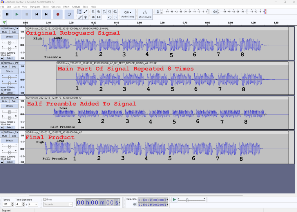
So firstly I observed my device for a few days, triggering it and pressing buttons etc. all while locked on to the frequency. Each time it did something I would record the time and make a high quality .wav recording of the signal.
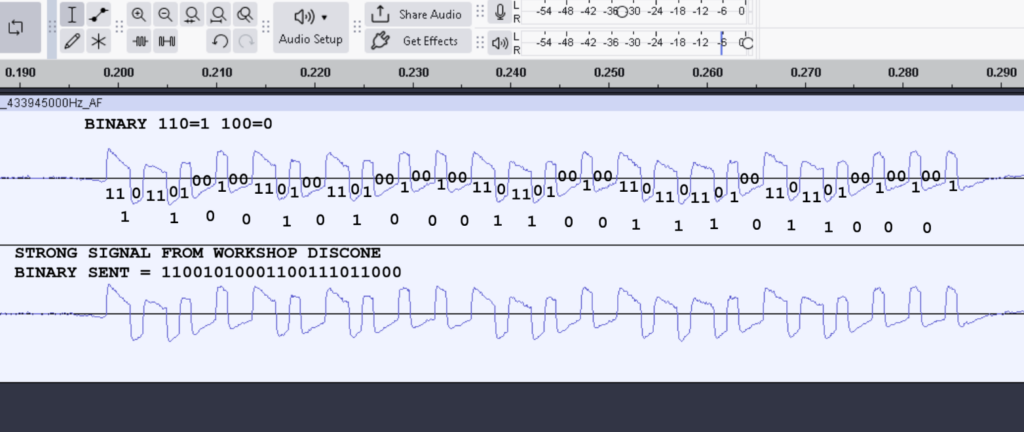
Once I had learnt a few of the patterns and habits of the device i was able to use this in conjunction with the recorded wave files in audacity to start putting meaning to the patterns of bits and bytes.
Though to make my life a bit easier I calibrated Universal Radio Hacker for my RTL SDR and mad some recordings using some .complex16s files.
The nice thing about URH is that it tries to figure out the patterns for you but I find there’s always a bit of manual labour needed so clankers-0 meatsacks-1 in this regards
URH helped clean up the signal a bit but I still needed to make some fine tuning adjustments and re record the signals a few times with different crystal offsets.
Eventually I got decent results and was able to easily read the bitstream.
So the basic signal is 1x preamble then 8x repeating pattern containing the id and type of signal being sent.
looks like this:
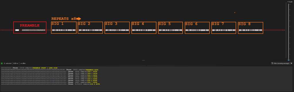
Now everything is about timing. The preambles timing is very different to the payloads timing sure you can just grab the payload and call it a day but the preamble is critical in this day and age. It helps prevent false positives and also adds a bit of time so that the listener can “wake up” and grab the signal reliably so it has and important purpose.
So I used URH since it captures the timings in μs where Audacity can’t really show you accurate timings.
And I came up with the values like in the picture.

This is a nice and simple AM signal to reverse engineer and so far I have not seen anyone else do this for this specific signal so I think I’ll add it to the RTL_433 devices list.
Now once we understand the signal we need to send that signal and receive that signal.
I have done this in bare-metal C programming for the Attiny, STM8 and STM32 microcontrollers as well as added the decoding library to the RTL_433 project on Github.
The cool thing about this was that now I got to extend my bit banging knowledge using bit arrays and shifting bits around. Plus really simplicity is genius in this case. complexity just confuses an already confusing pattern of radio waves, the simple solution is always there as humans we are mostly just to dumb to see it and require time running our biological processors thinking about it until one night suddenly there’s a solution.
The main purpose was to make a cool system for myself at the time but now the secondary objective is to get more people interested in Radio and signals, SDR making plugins etc.
Reverse engineering this signal required multiple different skills and the ability to learn new things so it’s a wonderful educational and useful thing to do with a youngster.
In my opinion it opens the door to curiosity about further complex signals in a moderate way, the individual could then take up more demanding tasks like decoding FSK and other more complex signals like digital voice DMR as an example.


