
#136 STLink V2 Clone Mod
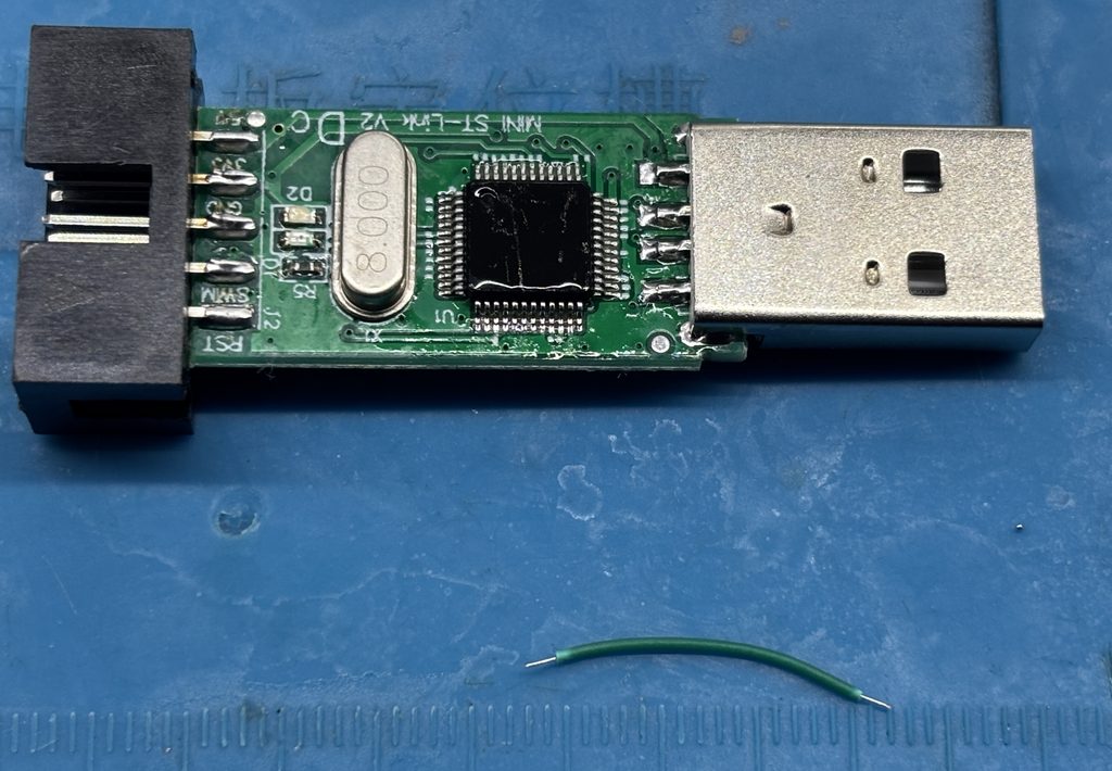
Years ago I purchased the original ST-Link V2 programmer to program STM8 and STM32 devices. The programmer worked ok but had a few major pains…
- Sometimes I had to power my IC’s externally and also have the programmer connected
- The connectors were not marked
- The connectors were made for specific plugs and were a pain because of this reason
- The programmer was large and round
All these issues while a cheap clone that’s about 4-5 times smaller with a better connector and a smaller form factor existed, what’s going on here?
Well the chepie also has its own problems like:
- Not having the correct RST pin connector
- Not having a SWO pin broken out
- Sometimes ST-link upgrade firmware bricks it
- Most of the time they have GD ICs or similar instead of the STM32F103
Since the V3 ST has released a V3 variant dongle like programmer which is great but I think they lost out on releasing that product many years ago it’s a little too late.
Needles to say the ST-Link V2 Clone is still extremely popular and very affordable especially for poor peasants like I was all those years ago. When every cent counts and you have real word problems affecting you’re life you don’t have time for enshitified programmers making your already underpaid underappreciated and suffering intern engineering job any harder especially after being on the 2AM call list for the 3rd week in a row.
The easiest option would be to just get a V3 but at that time I simply could not… so how can we improve the ST-Link V2 Clone?
Well there’s a few modifications that can be done just by soldering some wires, extra resistors can be added for a nice safety margin but I wont bother for this demonstration.

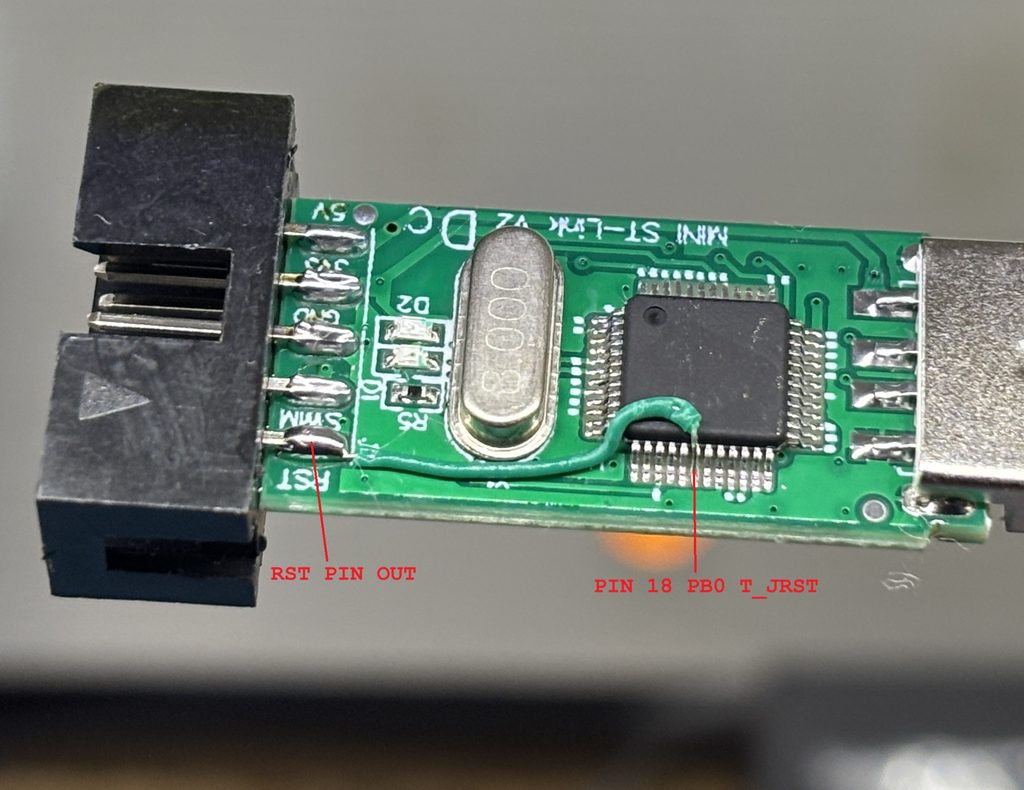
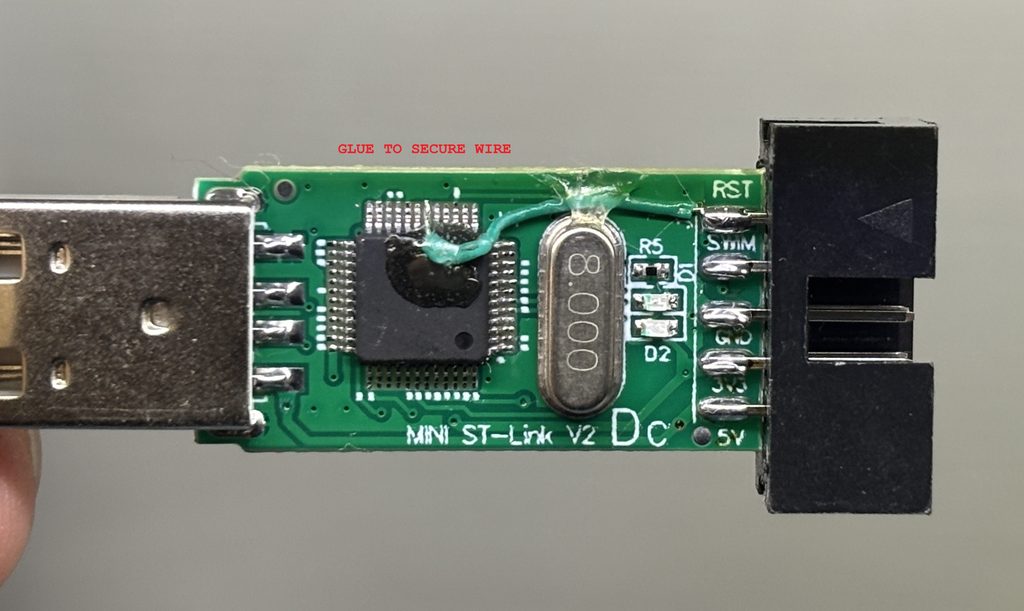
First off is the HW(Hard Ware) reset. The cheap clones do not have it connected to the RST Pin when the STM32 Pins (SWDIO,SWCLK) are used, it works fine for the STM8 pin connection.
Using the original ST-Link V2 schematic all we have to do is solder the pin PB0 T_JRST with a wire to the RST break out pin. See the picture below
Now to convert a pin into SWO all we need to do is sacrifice one of the power pins on the ST-Link V2. Here I break the trace of one of the 5V pins (I use 3.3V mostly anyway) Now solder a wire from PA10 T_SWO to the old 5V break out pin and that’s it.

reference links: